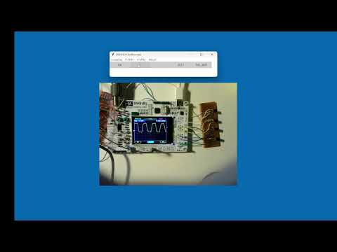
Controlando el osciloscopio DSO183 de JYETech mediante PC usando el CH32V003
Hace ya un tiempo he usado el frontend analógico que proporciona el pequeño osciloscopio DSO183 de JYETech para Techo. La pega es que el control del acoplamiento y la sensibilidad son manuales (mediante los switchs deslizables), así que había que probar a controlar esto también desde el PC. La verdad que ha ido bien, pero tiene ciertas limitaciones.
Limitaciones hardware
Como he usado un relé, G6K-2F, solo tengo dos estados y los switchs deslizables tienen tres:
- Acoplamiento
- DC
- AC
- GND
- SEN1
- 10mV
- 0.1V
- 1V
- SEN2
- x1
- x2
- x5
A mi no me hace falta tanto control puesto que el software que he desarrollado se vale de zoom digital (y funciona muy bien), así que para simplificar el circuito simplemente he optado por las siguientes opciones:
- Acoplamiento
- DC
- AC
- SEN1
- 10mV
- 1V
- SEN2
- x1
- x5
Esto tiene un problema : el osciloscopio físico tiene un offset en los operacionales y con estas configuraciones no se puede eliminar. A mi me es igual, porque todo el tratamiento es mediante software y esto tiene fácil solución. Esta también es una de las razones por las que desde el principio decidí que el hardware solo proporcionaría datos hardware… todo el tratamiento se haría mediante software por su enorme flexibilidad (aunque a veces tu jefe te pida que la llave inglesa que te pidió también envíe naves al espacio…).
Evidentemente puedes solucionar esto usando más relés… pero no sé si en realidad merece la pena. En mi caso no.
Botones
Al final también me puse a controlar los botones aunque no me hacen falta:
- OK
- +
- -
- SEL
Yo también añadiría el botón de reset, y es posible que lo haga…
Esquema
Relés
Como estoy usando el CH32V003 alimentado a 3.3V el G6K-2F es también de 3V. También fíjate que están los diodos de protección.
                            CPL
          ┌──────────────────|<|──────────────┐
          │                                   │
          │               + BOBINA -          │
 PC0      ├───────o 1──────[     ]──────o  8──┤  GND
          │                                   │
          │                                   │
 DC1 [1]──┼───────o 2                 7 o─────┼──[5] DC2
          │        \                     /    │
          │         \                   /     │
     [2]──┼──────────o 3             6 o──────┼──[6]
          │                                   │
 AC1 [3]──┼───────o 4                 5 o─────┼──[7] AC2
          │                                   │
          └────────────── G6K-2F ─────────────┘
                               SEN1
             ┌──────────────────|<|──────────────┐
             │                                   │
             │               + BOBINA -          │
 PC1         ├───────o 1──────[     ]──────o  8──┤  GND
             │                                   │
             │                                   │
 10mV_1 [1]──┼───────o 2                 7 o─────┼──[5] 10mV_2
             │        \                     /    │
             │         \                   /     │
        [2]──┼──────────o 3             6 o──────┼──[6]
             │                                   │
   1V_1 [4]──┼───────o 4                 5 o─────┼──[8] 1V_2
             │                                   │
             └────────────── G6K-2F ─────────────┘
                               SEN2
             ┌──────────────────|<|──────────────┐
             │                                   │
             │               + BOBINA -          │
 PC2         ├───────o 1──────[     ]──────o  8──┤  GND
             │                                   │
             │                                   │
   x1_1 [1]──┼───────o 2                 7 o─────┼──[5] x2_2
             │        \                     /    │
             │         \                   /     │
        [2]──┼──────────o 3             6 o──────┼──[6]
             │                                   │
   x5_1 [4]──┼───────o 4                 5 o─────┼──[8] x5_2
             │                                   │
             └────────────── G6K-2F ─────────────┘
Botones
Yo he utilizado un SS8050 porque tenía a mano suficientes, así que te tocará calcular a ti la Rb para que el transistor entre en las regiones de corte y saturación.
Todos los botones se controlan de la misma forma, así que simplemente pongo el dibujo de uno, con sus cuatro pads. Fíjate bien en la orientación de los transistores.
Para el control usamos las patillas PC3-6.
                           0 V
                           o                           o
                           |
                           |
                           E
                           ^
                          /
Control o───[ 3.3 kΩ ]───B  NPN       BUTTON
                          \
                          C
                          |
                          |
                          o                           o
                        +3.3 V
Ajustes
Lo que sí tendrás que hacer tras tener todo el montaje es ajustar C5 (C4 creo que no lo he llegado a tocar para nada) usando una onda cuadrada para contrarestar las capacidades parásitas y tener el máximo BW.
Código
En realidad este proyecto está en pañales y no debería mostrar el código, pero para que os hagáis una idea, estoy utilizando el esquema habitual de siempre:
main.c
#include "debug.h"

#include "dso183_driver.h"
#include "parser.h"
#include "usart.h"

/*********************************************************************
 * @fn      main
 *
 * @brief   Main program.
 *
 * @return  none
 */
int main(void)
{
  NVIC_PriorityGroupConfig(NVIC_PriorityGroup_1);
  SystemCoreClockUpdate();
  Delay_Init();

  USARTx_CFG();
  dso183_driver_init();
  parser_init();

  while(1)
  {
    // Parseado de los comandos
    if (parser_command_ready())
    {
      char cmd = parser_get_command();
      int opt = parser_get_int_from_command();

      switch (cmd) {
        case 'b':
          dso183_driver_buttons(opt);
          break;
        case 'c':
          dso183_driver_coupling(opt);
          break;
        case 's':
          dso183_driver_sen1(opt);
          break;
        case 'x':
          dso183_driver_sen2(opt);
          break;
      }
      parser_reset();
    }
  }
}
driver.c
#include "dso183_driver.h"

#include <ch32v00x.h>

enum {dc, ac};
enum {mV, V};
enum {x1, x5};
enum {btnOk, btnM, btnm, btnSel, btnSelAju};

// --------------------------------------------------------
void dso183_driver_buttons(uint8_t opt)
{
  switch (opt)
  {
    case btnOk:
      GPIO_WriteBit(GPIOC, GPIO_Pin_3, Bit_SET);
      Delay_Ms(250);
      GPIO_WriteBit(GPIOC, GPIO_Pin_3, Bit_RESET);
      break;
    case btnM:
      GPIO_WriteBit(GPIOC, GPIO_Pin_4, Bit_SET);
      Delay_Ms(250);
      GPIO_WriteBit(GPIOC, GPIO_Pin_4, Bit_RESET);
      break;
    case btnm:
      GPIO_WriteBit(GPIOC, GPIO_Pin_5, Bit_SET);
      Delay_Ms(250);
      GPIO_WriteBit(GPIOC, GPIO_Pin_5, Bit_RESET);
      break;
    case btnSel:
      GPIO_WriteBit(GPIOC, GPIO_Pin_6, Bit_SET);
      Delay_Ms(250);
      GPIO_WriteBit(GPIOC, GPIO_Pin_6, Bit_RESET);
      break;
    //
    case btnSelAju:
      GPIO_WriteBit(GPIOC, GPIO_Pin_6, Bit_SET);
      Delay_Ms(4000);
      GPIO_WriteBit(GPIOC, GPIO_Pin_6, Bit_RESET);
      break;
    //
  }
}

// --------------------------------------------------------
void dso183_driver_coupling(uint8_t opt)
{
  switch (opt)
  {
    case dc:
      GPIO_WriteBit(GPIOC, GPIO_Pin_0, Bit_RESET);
      break;
    case ac:
      GPIO_WriteBit(GPIOC, GPIO_Pin_0, Bit_SET);
      break;
  }
}
...
// --------------------------------------------------------
void dso183_driver_init()
{
  GPIO_InitTypeDef GPIO_InitStructure = {0};

  RCC_APB2PeriphClockCmd(RCC_APB2Periph_GPIOC, ENABLE);
  GPIO_InitStructure.GPIO_Pin = GPIO_Pin_0 | GPIO_Pin_1 | GPIO_Pin_2 | GPIO_Pin_3 | GPIO_Pin_4 | GPIO_Pin_5 | GPIO_Pin_6;
  GPIO_InitStructure.GPIO_Mode = GPIO_Mode_Out_PP;
  GPIO_InitStructure.GPIO_Speed = GPIO_Speed_30MHz;
  GPIO_Init(GPIOC, &GPIO_InitStructure);

  Delay_Ms(10);
  GPIO_WriteBit(GPIOC, GPIO_Pin_All, Bit_RESET);
}
Demostración
Aquí tienes un vídeo demostración para ver su funcionamiento.